For surface backpressure Managed Pressure Drilling (MPD) drilling operations, it is possible to circulate minor influxes using the MPD equipment, without resorting to conventional “well control” with a closed Blow Out Preventer (BOP).
Still, the MPD equipment has a significantly lower pressure rating than the blow-out preventer, and a less rigorous testing regime than well control equipment. Due to this, the decision of circulating out an influx through MPD equipment should not be taken lightly.
Numerous guidelines and tools such as the “MPD Operating Matrix” and “Influx Management Envelope” are at the core of decision making related to dealing with minor influxes using the MPD equipment.
MPD Operating matrix
To help with this decision making, the Bureau of Safety and Environmental Enforcement (BSEE) released guidelines for drilling operations in the Gulf of Mexico in 2008. One of the recommendations was to develop a “MPD Operating Matrix” (also known as the “MPD Well Control Matrix (WCM)”. The “MPD Operating Matrix” is well known and used extensively on most MPD operations worldwide. An example of an MPD Operating Matrix is shown below.
The MPD Operating Matrix aims to answer the following question:
“At my current surface pressure, and having taken an influx of a known size, can this influx be circulated through the MPD equipment, or should the BOP be closed, and conventional well control operations commence?”
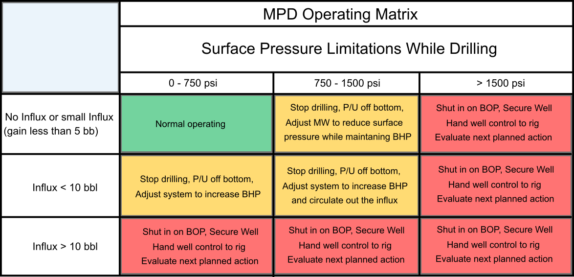
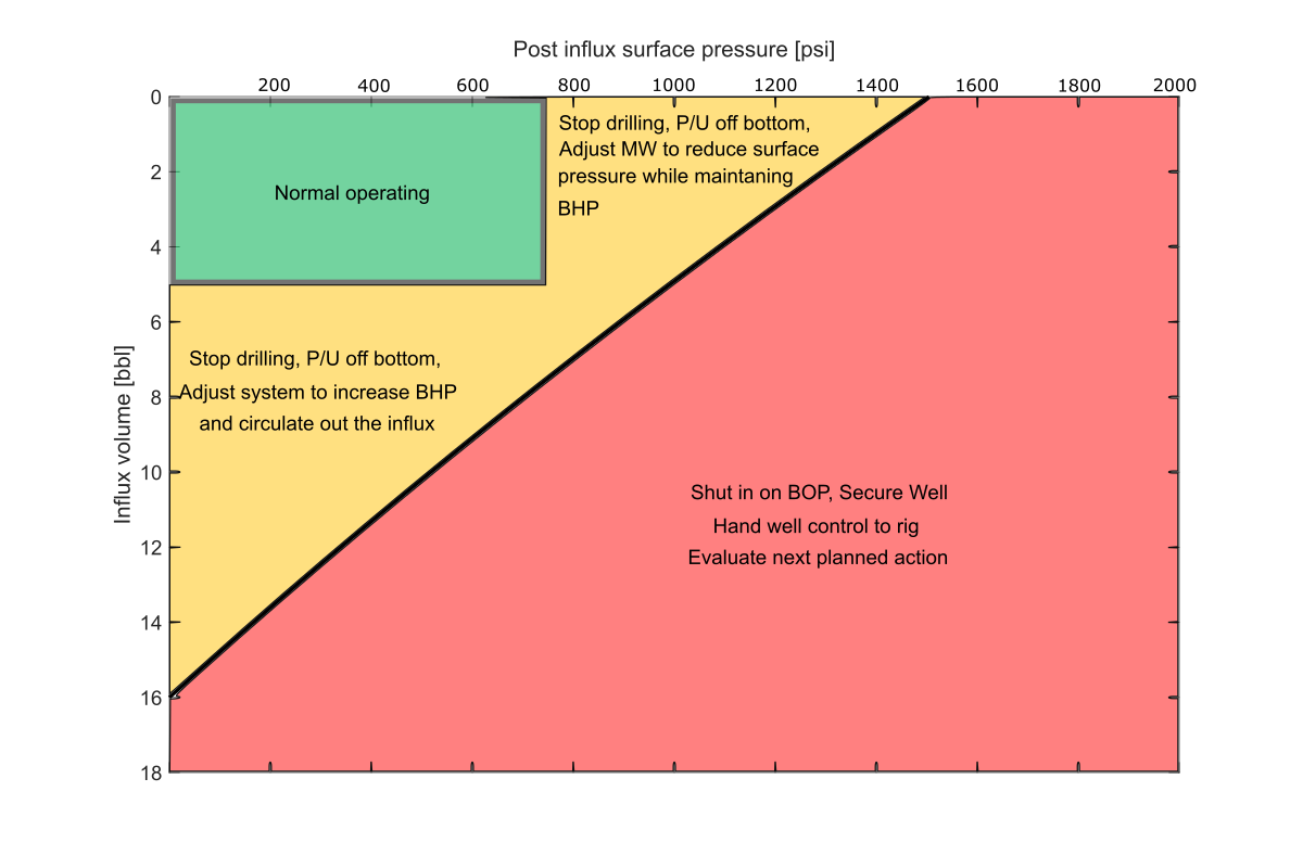
MPD Operating Matrix. Are you OK to circulate your influx using MPD equipment or should BOP be closed, and rig commences well control operations? Note that the pressures and volumes shown in this matrix are for illustration only. Actual values should be the result of depth specific calculations
The limits in the Operating Matrix are usually given by the surface pressure limit, expected surface pressure in operation, and typical influx detection algorithm limitations. The MPD Operating Matrix is designed to provide post influx guidance. Once an influx has been suppressed, the calculated or measured influx volume and resultant surface back pressure is cross referenced to the matrix to determine the next recommended actions (yellow or red zones).
Isn’t this good enough?
The matrix provides good guidance; however it has one serious drawback: If the influx volume and new surface back pressure recommends to circulate the influx using MPD equipment (yellow or green zone), it typically does not consider that if the influx is gas, surface pressure will have to be increased when the influx is circulated to the surface. Increased surface back pressure during circulation is required to maintain bottomhole pressure constant and avoiding a secondary influx.
In other words, it might say you can circulate using MPD equipment, but increasing back pressure during the circulation could push closer and closer to the surface limit, requiring a transition to the BOP and conventional well control practices in the middle of what is already a complex operation.
This issue was pointed out independently in the papers:
“The MPD Well Control Matrix; What is Actually Happening” by Mir Rajabi et. al. in 2014
“Evolution of the MPD Operations Matrix: The Influx Management Envelope” by Culen et. al. in 2016.
The solution to this is simple:
The “Influx Management Envelope” or IME for short.
IME?
The overall “look” of an IME is deceptively simple and similar to a MPD Operating Matrix, but the question it answers is the key to its improvement over the Operating Matrix.
Below is the original question from above, with the key differences for the IME highlighted in bold:
“At my current surface pressure and having just taken an influx of a known size. At my current depth, can this influx be circulated through the MPD equipment all the way to the surface, or should the BOP be closed, and conventional well control operations commence?”
As it happens, knowing “post-influx” surface pressure and influx volume right after the influx is taken, it is possible to predict what the peak “future” surface pressure will be.
If one were to simulate multiple combinations of post influx pressure and influx volume including circulation to the surface, an interesting finding appears:
There are multiple combinations of post-influx pressure and influx volume that will result in the imposed surface pressure limit. If one were to plot all these combinations it usually takes the form of a near straight line.
Superimposing a line like this, called the “surface limit”, on the conventional MPD Operating Matrix (assuming that the axis can be treated as “continuous”) and the same surface limit of 1500psi looks like this:

The IME has a “surface limit” line that considers the increase in pressure when the influx is circulated to the surface. In many cases there is a significant part of the MPD Operating Matrix outside the IME surface limit line. Influxes in this region can exceed surface pressure limits when circulated with MPD equipment. There is often also an “unexploited” region in the IME vs the Operating Matrix at low post influx pressure.
The above clearly illustrates that considering the required increase in pressure when circulating the influx to the surface, Influx Volume and Surface Pressure should not be considered “independent” when considering the criticality of an influx. Whether an influx can be circulated to the surface with MPD equipment while considering the required additional surface pressure is a combination of the two variables for a given well.
Does this mean we should stop doing a “Operating Matrix”?
No, not necessarily. But it does mean that in the example above, ideally the Operating matrix should have a surface limit pressure/influx volume limit that makes it fit “inside” the IME surface limit. In other words, some calculation should be performed when using the Operating matrix. Doing this one can ensure that the lower right yellow corner represents a volume/pressure combination that could be circulated to surface with MPD equipment for a given well, without violating the surface limit.
An Operating matrix like this would be perfectly fine, but often having a relatively small window for influx circulation, due to neglecting a large region where the influx could be safely circulated over MPD equipment if considering the IME.
To remedy the issue of the MPD Operating matrix being outside the IME surface limit line, a calculation based MPD Operating matrix can be made. This would consider the required extra surface pressure when circulating the influx to surface. When this is performed, the MPD operating matrix often become rather “small”, and there are large regions outside of it where the influx could be safely circulated if one where to consider the IME surface limit.
How do I use an IME?
Using an IME operationally is as simple as using the MPD Operating Matrix. Below is the IME for the case above, where the regions outside the Operating Matrix is exploited.
After an influx is taken, a point is plotted for the post influx pressure and influx volume. The region this point falls in determines subsequent actions.
IME from previous visualisation. Regions outside of the MPD Operating matrix is exploited.
What about my formation limits?
In operation, the surface equipment pressure rating is not the only pressure limit one should consider. In most cases there is also a formation pressure limit. Using the same approach as above, one will find that there is also a combination of post influx pressure and influx volume that will exactly hit my formation pressure limit. The pressure and volume combinations that hit the formation limit pressure also forms a near straight line, the “formation limit line”.
Bringing it all together
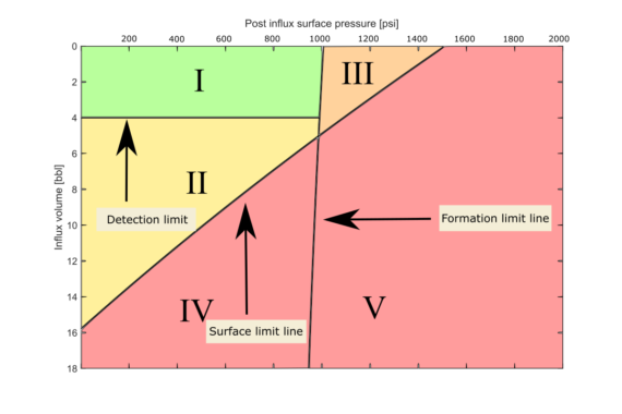
Considering both a surface pressure limit, formation pressure limit, and mapping out all the combinations of “post influx pressure” and influx volume that hit these, an IME can be constructed. An example of a full IME can be seen below.
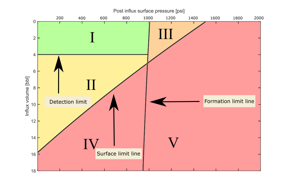
IME with surface and formation limit lines and annotated regions.
I. Below influx detection limit, no influx is detected, and operation continues as normal.
II. Influx detected and suppressed. Combinations of post-influx surface pressure and kick volume in this region will not exceed the specified surface-pressure limit when circulated to the surface and can be circulated out using the MPD equipment.
III. Influx/ post-influx pressure combinations in this region will exceed the specified formation pressure limit when circulated to the surface. The criticality of this depends on how the weak-point limit has been found, and the likelihood of an underground blowout if the limit is exceeded.
IV. Combinations of post-influx pressure and kick volume in this region will exceed the specified maximum surface pressure when circulated out, but the kick will not violate the weak-point pressure limit. The kick can be circulated with the MPD equipment initially, but then handed over to conventional well control once the influx has reached a pre-determined depth/ surface pressure.
V. Combinations of post-influx pressure and kick volume in this region will exceed both the MPD surface-pressure limit and violate the weak-point pressure limit. A kick in this region might prove challenging, even when doing conventional well control.
This seems like a lot of work
In terms of operational use, it can be argued that the IME is just as simple as the MPD Operating Matrix. Plot a point or point your finger at the “post influx pressure” and influx volume combination and see if that point is in the “red” region or not.
Of course, trying to calculate an IME by arbitrarily specifying post influx pressure and volume in a modelling tool to try to find the combination that hits the limits (as explained earlier) is a lot of work. Luckily, there are purpose-built tools out there that does all of this, making the generation of an IME just as simple as filling out the textboxes in a MPD Operating Matrix.
For further reading on how this can be done, see:
Berg, G.A. Evjen, N. Velmurugan, M. Culen, The Influx-Management Envelope Considering Real-Fluid Behavior, SPE Drilling & Completion. (2020). https://doi.org/10.2118/198916-PA
Summing it up
MPD equipment can circulate out small influxes while maintaining constant bottomhole pressure. Due to the smaller pressure ratings and less rigorous testing regime on MPD equipment, a MPD Operating Matrix should be the bare minimum for any MPD operation.
Using an MPD Operating Matrix to decide whether to circulate out an influx through MPD equipment can have significant limitations.
As most MPD Operating Matrix’s fails to consider the required “pressure increase” when the influx gets closer to surface. Many influxes that would be considered “OK for MPD” in the Operating Matrix, will eventually have to be handed over to conventional well control.
Using an MPD Operating Matrix that has limits based on influx circulation calculations for a given well remedies this but leaves little room for circulating an influx with MPD equipment in many cases.
The Influx Management Envelope remedies a lot of these issues with the MPD Operating Matrix, but still maintains the same “look” as the MPD Operating Matrix, making it operationally as simple to use, although more complex to generate if not having a purpose-built tool for calculating it.